


 Durcor
Durcor
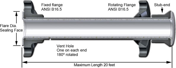
Restrained Systems
When it is necessary to restrain the piping system with anchors, the ability of the Durcor piping to absorb the resultant compressive loads needs to be determined. These compressive loads are caused by restricting the thermal expansion of the piping and pressure thrust acting on the pipe from fluid pressure. Guides are recommended whenever Durcor is fully restrained by anchors to provide lateral support. Guide spacing will be provided in this section.
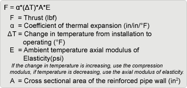
Thrust attributable to temperature changes in anchored piping
The force created by fully anchoring Durcor pipe and introducing a temperature gradient is calculated by:
Example: Anchored 2” Durcor will operate at 150°F; how much thrust will be exerted on the pipe?
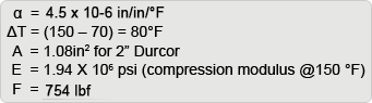
Reinforcement area of 2” Durcor pipe is 1.08in2.
Pipe stress is force/area = 1,123 lbf/1.08in2 = 1,940 psi
Allowable pipe stress is the axial tensile design strength, or 10,875 psi.
| Restrained Thermal End Loads | |||||
|---|---|---|---|---|---|
| Above data is based on reduction of compression modulus of elasticity by 6,000 psi/°F | |||||
| Size (in) | 100 °F | 125 °F | 150 °F | 175 °F | 300 °F |
| Thermal End Load (lbs) | Thermal End Load (lbs) | Thermal End Load (lbs) | Thermal End Load (lbs) | Thermal End Load (lbs) | |
| 1 | 149 | 277 | 386 | 475 | 621 |
| 1-1/2 | 217 | 404 | 563 | 693 | 906 |
| 2 | 272 | 508 | 707 | 870 | 1,137 |
| 3 | 559 | 1,044 | 1,454 | 1,788 | 2,338 |
| 4 | 791 | 1,477 | 2,056 | 2,529 | 3,306 |
| 6 | 1,426 | 2,662 | 3,706 | 4,559 | 5,960 |
| 8 | 2,142 | 3,997 | 5,565 | 6,847 | 8,951 |
| Restrained Pipe End Loads from Pressure Thrust | |||
|---|---|---|---|
| Size (in) | 50 psi (lbf) | 150 psi (lbf) | 275 psi (lbf) |
| 1 | 42 | 126 | 231 |
| 1-1/2 | 98 | 294 | 540 |
| 2 | 155 | 465 | 852 |
| 3 | 340 | 1,020 | n/a |
| 4 | 585 | 1,755 | n/a |
| 6 | 1,305 | 3,915 | n/a |
| 8 | 2,245 | 6,735 | n/a |